HOOKING UP THE SSC-32
Let's get started...
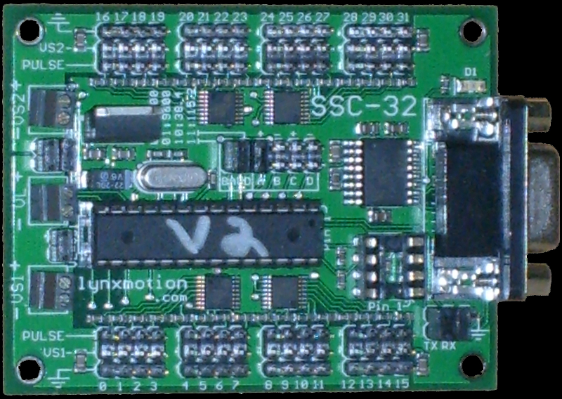
First, you should be looking at your SSC-32 board. It looks like this:
You will need some way to connect this to your computer. It has a jack for a Serial cable. They look like this:
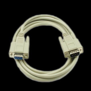
Getting one of those is your best bet. They are plentiful and cheap on ebay.
However, if your computer does not have a serial output, you may need a USB to Serial adapter (shown below:
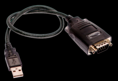
These also abound on ebay.
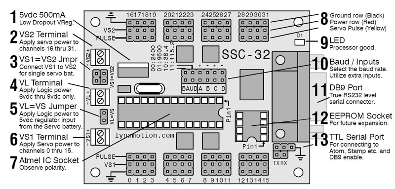
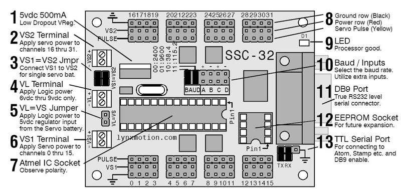
the next step is to make sure you have all your jumpers in place. To make it easier than looking at the actual board, here is a diagram of the board with NO jumpers in place:
Your board will come with jumpers on, but you may not want to keep them all in place.
First thing is to be sure that the Baud Rate is set correctly. Otherwise, your computer will not talk to the board.
The Baud Rate is determined by the jumpers in the center of the board in the area labeled "10"
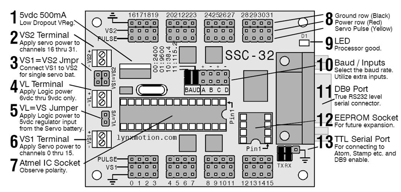
With the jumpers in this position, your board will be set for a Baud Rate of 115200, which is what the computer should expect.
You will notice that 2 jumpers are also in place in area 13 in the lower right hand corner. They should come like that.
These have nothing to do with the baud rate, but just leave them there in place in the manner shown.
Now, you should make sure that both VSA and your computer in general have the com port that you are using set to the same Baud Rate.
Let's check your computer's Com Port first. We will assume that you have a standard computer with one serial output which is called by default, "COM1"
First, click the "Start" button on your computer desktop. (By the way, VSA will not run on a Mac, so we are only talking Windows machines here).
After Clicking Start, click on the "RUN" icon. You will get a dialog box. Type in the following exactly as it appears on the next line, then click OK:
devmgmt.msc
That will open up your Device Manager, which should look like this:
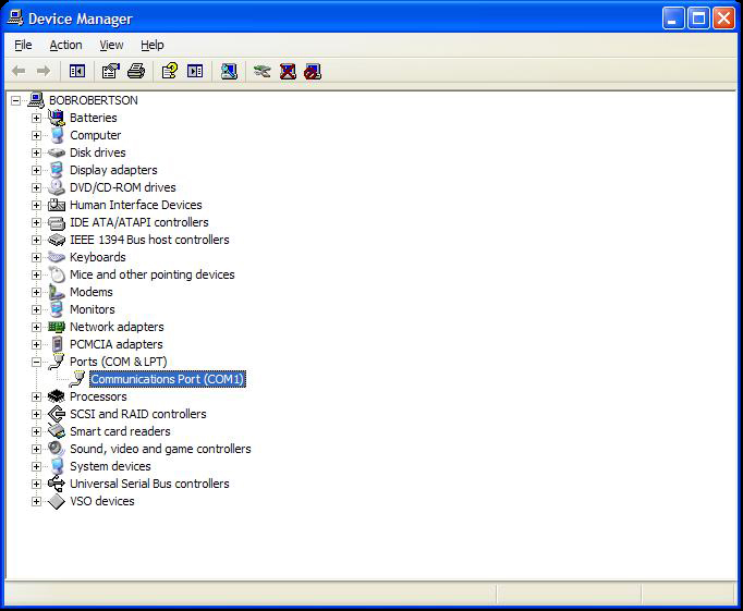
As shown above, expand the "Ports (COM & LPT) section by clicking on the small plus sign (+) to the left of it. Then double click on the "Communications Port (COM1)
That will give you something that looks like this:
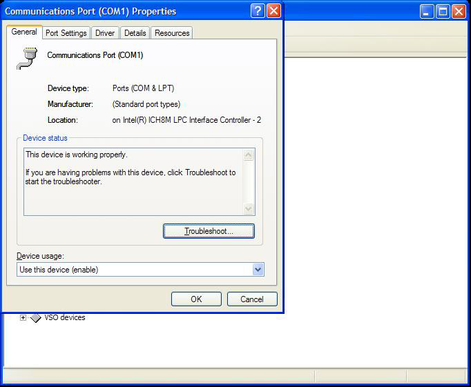
Click on the tab at the top of the Properties box that says, "Port Settings". Now it should look like the picture below:
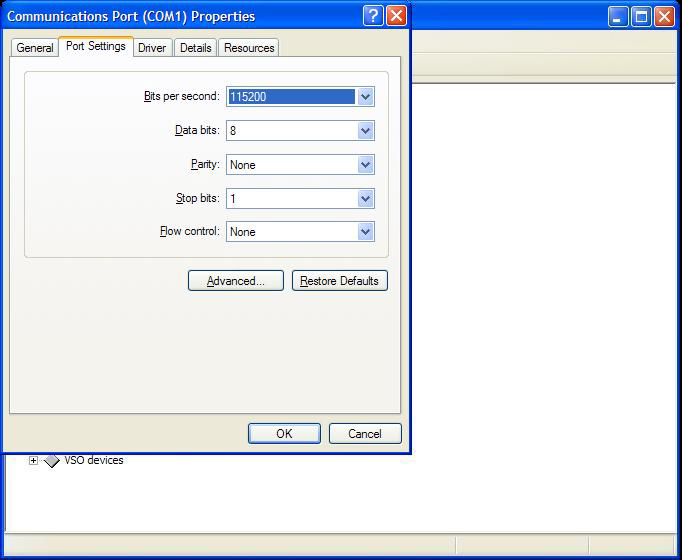
As shown above, make sure that the "Bits per second" line says 115200. If it does not, change it so that it does, and click OK.
Now, open up VSA. Go to "Tools" and then "Settings". You should see a box that looks like this:
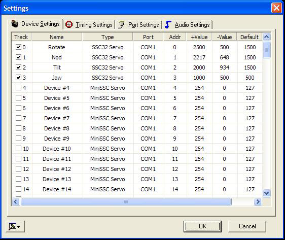
You will likely have other device names in there and maybe in a different order, but that is not important right now.
Just be sure that the "Port" column says "COM1" and the "Type" column says "SSC32Servo" for all the tracks that you are using.
Now Click on the "Port Settings" tab across the top of this box.
You should get a new box that looks like this:
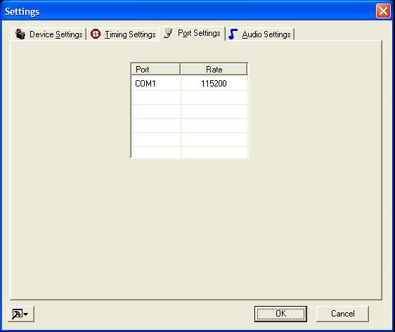
Again, make sure that COM1 is set to the rate you see above (115200). If it is not, double click on the number it is set for and select 115200 from the drop down menu that appears.
OK, now we are ready to hook up power.
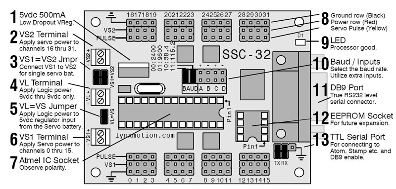
Let's look at the board again:
There are 3 separate Voltage input areas. In the center on the left is VL and is labeled Number 4. This stands for Voltage Logic, or the power that will run the actual board itself and power up the chips on the board. This input will accept any voltage between 6 and 9 VDC and requires only about half an amp of current. The other two voltage inputs are at numbers 6 and 2. They are VS inputs which stands for "Voltage to Servos" The VS1 input controls all the servos in the row across the bottom of the board. The VS2 input controls all the servos across the top of the board.
VOLTAGES FOR VS1 AND VS2 MUST BE EITHER 5VDC OR 6VDC. NEVER CONNECT ANY OTHER VOLTAGE AMOUNT HIGHER THAN 6VDC OR LOWER THAN 5VDC TO THESE INPUTS.
DOING SO CAN DAMAGE YOUR SERVOS AND POSSIBLY BURN THEM UP.
The good news is that you do not need 3 separate power supplies. It's all in how you set the jumpers and what kind of power supply you use.
Let's explain those jumpers now.
The most common jumper we would apply is the VS2=VS1 jumper labeled as number 3 in the diagram below:
Actually it is 2 jumpers, and I know that it says VS1=VS2 in the diagram, but when I look at the real board, it is printed the other way around. Whichever way it says it, those are the jumpers we are talking about.
This set of jumpers is simple. All it does is tie together all the servo outputs on the board to run from a single power supply.
To wire this correctly, you would put the 2 jumpers in place as shown above and hook up a 5 or 6vdc ONLY power supply to EITHER the VS1 OR the VS2 input. NOT BOTH.
Make sure your power supply provides enough current to drive all the servos you are using. A rule of thumb is that you should have 1/2 an amp per servo. So if you are using 12 servos (for example) you should have a power supply that produces either 5 or 6 VDC at AT LEAST 6 amps. It can be rated for more than 6 amps, but not less.
I need to repeat that the servos we use are meant to run on a voltage between 4.8 and 6 volts. NEVER any more than 6VDC. It is hard to find a 4.8 volt power supply, but 5VDC power supplies are plentiful, so you will most likely use that.
A note about current. I have had several callers ask me if they use a 5 volt power supply with too much current, will they burn up the servos.
The answer is NO! There is no such thing as too much current. You can have too much voltage, but not too much current. Current is a measure of available power. The servos will use what they need of that power up to the total available power of the supply. So if your supply is rated at 4 amps and (like the example above) you have 12 servos all pulling 1/2 an amp each, you will be trying to get 6 amps out of a 4 amp supply. The power simply won't be there. That can cause problems like the servos not having enough power to move the weight they are supposed to move. In some cases, it can even drag down the power supply and cause it to overheat.
In the same example, if you had a power supply that has an output of 5 VDC at 50 amps, your same 12 servos would use 6 of those 50 amps leaving you with 44 amps left over to run additional servos or whatever else. Everyone leaves that party happy!
Now back to the diagram above.
This setup as it is assumes that you are using 2 separate power supplies.
One for the VL (which can be any voltage from 6 to 9 VDC)
And another for the Power to ALL the servos (either 5 or 6VDC)
Now, let's complicate things a bit for the more adventurous among us.
Let's say that you want to simplify things a bit and only use ONE power supply for everything. I will talk about the advantages and disadvantages a little later on, but for now, let's assume you want to run the whole thing (SSC-32 board AND all the servos) from one single power supply.
Here is how it is done.
First, make sure your power supply has an output with enough current (amps) to run everything. All your servos AND the board itself. (Add 1/2 an amp just for the board).
Go back to the rule of thumb. 1/2 an amp per servo + 1/2 an amp for the board.
In the example we used earlier with 12 servos, that would be 6 amps for the servos and 1/2 an amp for the board. You would need a power supply that can provide 6.5 amps of current.
If you are using every servo output on the board (32 of them) you would need 16 amps just for the servos and 1/2 an amp for the board, so your power supply should be AT LEAST 16.5 amps or any amount greater than that.
Now here is the problem.
The servos will run on 5 or 6 volts, but the input to the SSC-32 board must be a Minimum of 6 VDC
Since you can't use MORE than 6 VDC for the servos and you can't use LESS than 6VDC for the board, that means that you have to use a power supply that will give you 6VDC at whatever current (amps) you need according to the formula.
These do exist, but they are much harder to find and pricier than the 5VDC power supplies.
In any case, let me show you how you would hook up your 6VDC power supply to the SSC-32 board to run everything from this one supply. Refer to the picture below:
Here you will see that the VL=VS jumper is now in place (labeled #5). This jumper takes the voltage that is going into VL (Always be careful to get the polarity correct) and sends it directly to the VS1 AND VS2 inputs.
With the configuration above, you would need the supply hooked up to the VL inputs only.
That's it!
But it would have to be a 6VDC Power supply with enough current to run all your servos and the board.
Now for advantages or each setup....
1. Advantages of the single power supply setup:
a. One less thing to plug in
b. Slightly simplified wiring
c. If you find a good deal it may cost less than two conventional voltage power supplies
2. Advantages of the 2 power supply setup
a. You have more choices of power supplies to buy and they are cheaper
b. You have the option to turn off power to the servos while not in use thereby extending the life of the servos
Still have questions?
Please read the booklet HERE
Still have questions even after reading the manual????
Give me a call and I will be happy to help you as best I can.
978-790-1367